Foundation slab on the combination of Stone Columns and Compaction Grouting
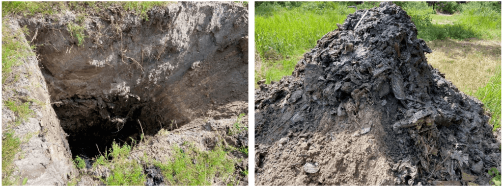
The project challenge was a layer of debris close to the surface at a depth of 0.5 to 3 m. Buried debris was predominantly household garbage, including plastics, glass bottles, fabric, and other miscellaneous wastes, mixed with sand in varying proportions. Images of test excavations of the debris layer are shown in the pictures below.
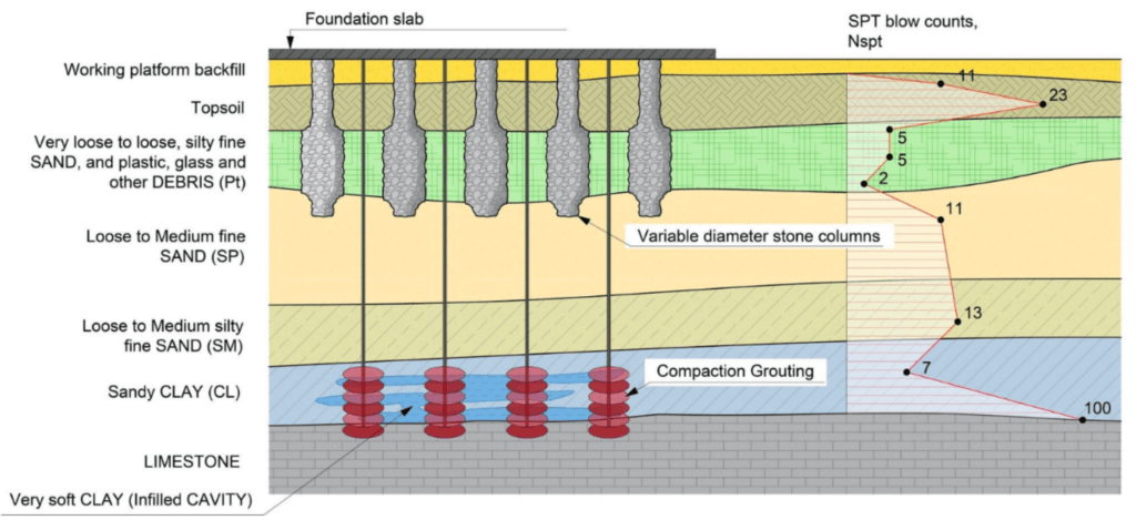
In addition, during geological surveys, infilled cavities were found at some sites, at depths ranging from 8.5 m to 10 m, near the limestone. Evidence of an infilled cavity is the data by weight-of-rod SPT blow counts.
The load from the building was distributed to a large depth, and therefore the presence of very soft clay (infilled cavity) was the cause of additional settlement.
The original recommendations of the geotechnical report were supporting the load-bearing columns and walls of the building using piles with tips embedded in the limestone formation to a depth of up to 12-13 m.
Instead of using piles to support the floor slab, the initial geotechnical report recommended that the floor slab be constructed as a slab-on-grade member with the following measures: Proof-roll using a Heavy Vibratory Roller, Waiting Period after Fill Placement (2 months), Pre-loading Soft Areas using Additional Surcharge Fill (2 months), Settlement Monitoring, and Floating Floor Slab.
The recommendations presented did not fit into the customer’s budget and schedule, so he was looking for alternative solutions.
Solution:
Soilmechanics studied in detail the geotechnical report with all available data and applications and performed a standard set of geotechnical calculations using analytical methods, as well as finite element calculations using Plaxis 3D.
Soilmechanics calculations confirmed that it was possible to control deformations according to the customer’s requirements. This required stabilization of the infilled cavity using Compaction Grouting and installing Stone Columns to a depth of up to 5m.
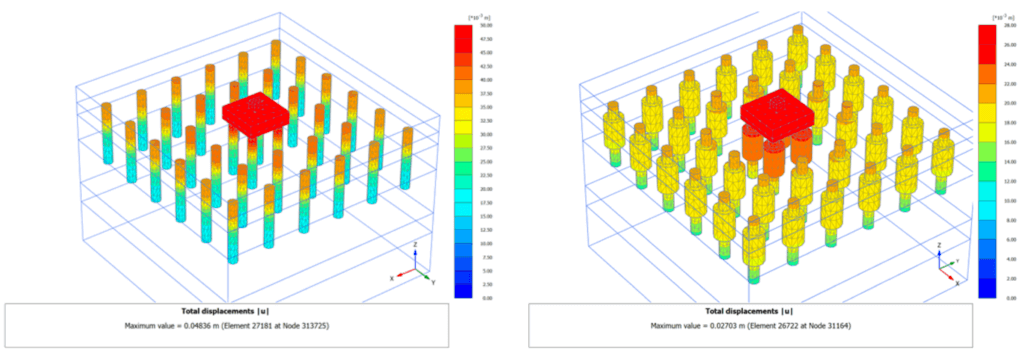
The use of Betterground’s quality control system during installation allows the performing of variable-diameter stone columns in depth, depending on the stiffness of the soil. The use of variable-diameter stone columns results in a more uniform soil stiffness. This solution has often proven effective in weak soils of limited thickness.
A comparison of Plaxis 3D calculation results for constant-diameter and variable-diameter stone columns is shown in Figure 2 below. A sketch of an implemented ground improvement solution is shown in Figure 3.
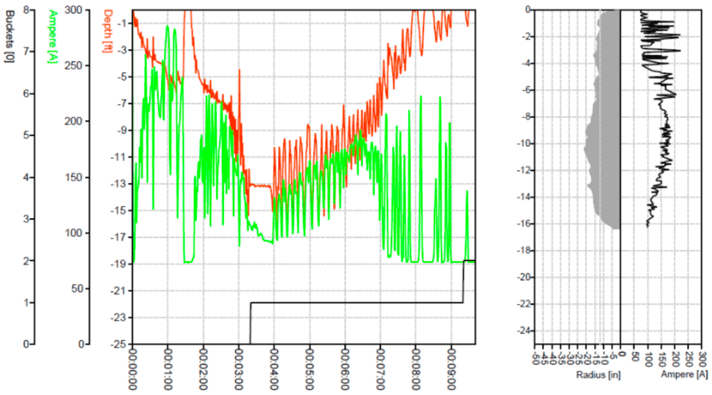
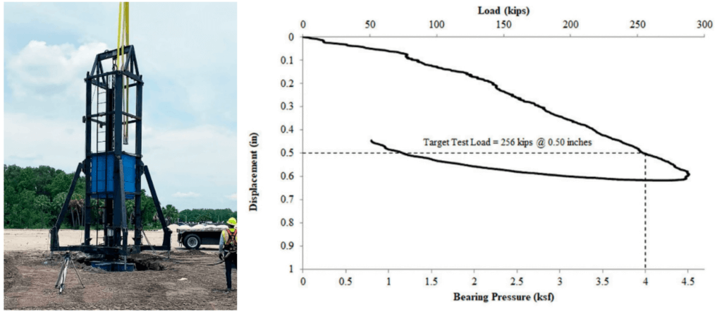
The quality of the stone columns has been proven using a quality control system during installation (Figure 4) and Rapid Load Tests (RLT) on an 8ft by 8ft steel plate after installation (Figure 5).
Facts
The recommendations and calculations developed by Soilmechanics allowed to the customer to switch to the stone columns solution for the foundation of the building, which saved a lot of money and reduced the time of work.
